Design guide for injection molding
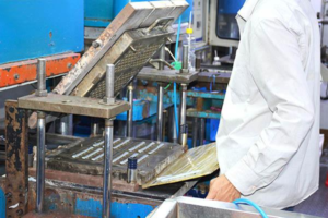
Injection molding is a formative manufacturing technology, i.e. material is formed from an amorphous shape into a fixed shape defined by a mold tool. Almost every plastic part created today is by injection molding as it allows identical parts to be created in huge numbers, in a short space of time, and at very low cost per part.
Best practice design guides aim to help create complex shapes while:
• Allowing plastic to flow easily and uniformly around the part.
• Allowing the plastic to cool quickly and evenly, resulting in a stable and accurate part.
These general tips will improve part quality, mold ability and cycle time based on known implementation and characteristics of the injection molding process.
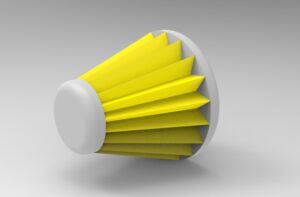
Draft angle
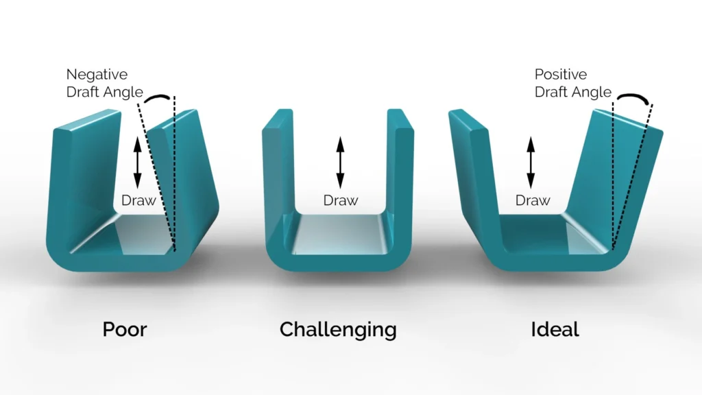
Draft, or the application of a slight taper to every surface in the direction of pull on an injection-molded part, is a small and even tedious design element — but one that’s vital to the success of a project. To visualize draft, envision an ice cube tray: the slight taper allows ice cubes to slide out easily without falling victim to excessive suction or friction. Parts that are lacking the appropriate amount of draft — or a suitable draft substitute — will not properly eject from the mold.
What’s more, draft protects the part from damaging friction, reduces wear and tear during the ejection process, helps ensure a uniform finish, and reduces costs by avoiding the need for complex injection setups. Fortunately, no toolmaker would make a part without draft. For that reason, designing for optimized draft angles doesn’t just mean adding draft; in most cases, draft is a given. Rather, optimizing draft means carefully incorporating draft so that it adds to, rather than interferes with, the design and look of the final part.
The minimum draft angle for any given part is largely driven by the depth of draw, the wall thickness, the material’s shrink rate, and the surface finish or texture that is to be applied. As a general rule, a draft angle of 1.5 to 2 degrees is required for most parts, but draft should average about an additional degree for each extra inch of part depth. Note that if a part is very small, there’s some more flexibility to decrease draft below 1.5 degrees. However, for most parts, 1.5 degrees is the minimum draft requirement.
That said, texture also plays an important role in determining draft. Many injection-molded parts have a leather grain or other texture applied to their surface for aesthetic purposes; however, depending on how deep the texture is, the draft angle may need to be increased to ensure the texture won’t be scraped off or damaged during the ejection process.
Automobile interiors are a strong example of strategically-applied draft. Most modern automobile interiors are injection-molded but feature a leather grain texture; a careful eye can discern that the texture depth varies throughout the part in order to accommodate changing draft, but it’s barely noticeable. On the other hand, many cheaply-made consumer goods have visibly different textures throughout the part or even texture that has been noticeably scraped off.
Wall thickness
If you take apart any of the plastic appliances around your home (as most engineers probably did as children) you’ll notice that the walls for most parts are about 1 mm to 4 mm thick (the optimal thickness for molding), and uniform for the entire piece. Why? Two reasons.
First of all, thinner walls cool faster, shortening the cycle time of the mold, the amount of time it takes to make each part. If a plastic part can cool faster after the mold is filled, then it can safely be ejected sooner without warping, and because time on the injection machine costs money, the part is less expensive to produce.
The second reason is uniformity: In the cooling cycle, the outer surface of a plastic part cools first. Cooling causes contraction; if the part is of uniform thickness, then the entire part will shrink away from the mold uniformly as it cools, and the part comes out smoothly.
However, if the part has thick and thin sections next to each other, then the molten center of the thicker area will continue to cool and contract after the thin areas and surfaces have already solidified. As this thick area continues cooling, it keeps contracting, and it can only pull material from the surface. The result is a little dimple on the surface of the part called a sink mark.
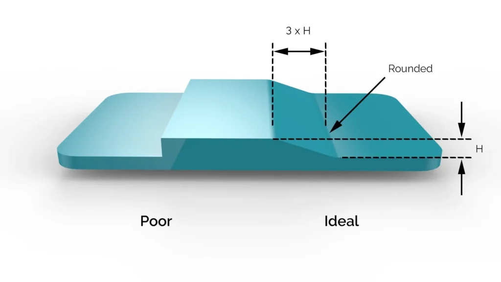
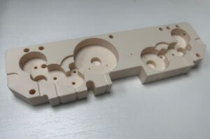
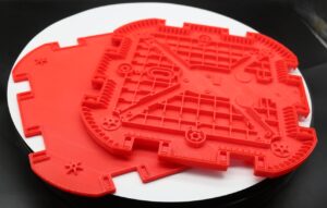
Happily, thick walls have some simple solutions. The first thing to do is to notice the areas which are a problem. In the part below, you can see two common issues: thickness around screw holes, and thickness where strength is needed in the part.
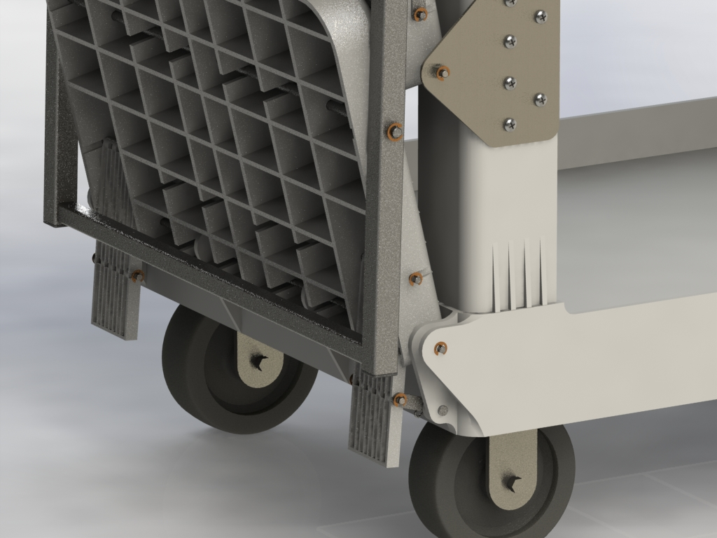
For screw holes in an injection molded part, the solution is to use “screw bosses”: a small cylinder of material directly around the screw hole, tied to the rest of the housing using a rib or a flange of material. This allows for more uniform wall thickness and fewer sink marks.
When an area of the part needs to be especially strong, but the wall is too thick, the solution is similarly simple: ribbing. Instead of making the entire part thick and difficult to cool, thin the exterior face into a shell, then add vertical ribs of material to the interior for strength and rigidity. In addition to easier molding, this reduces the amount of required material, reducing costs.
Radii
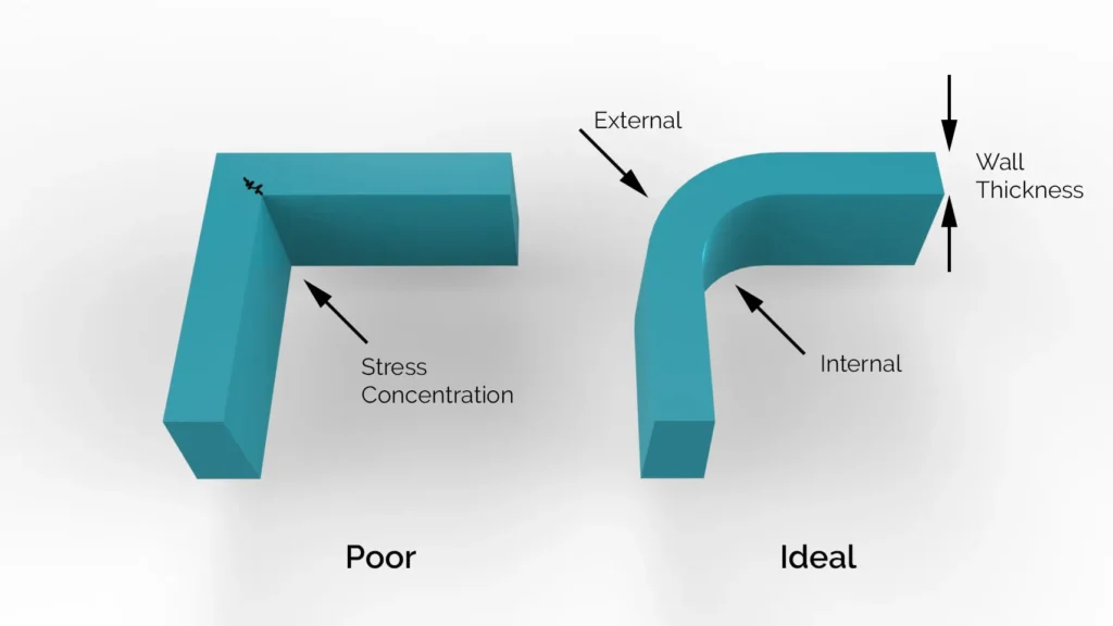
Correct placement of corner radii in injection moulding design creates strong, high-quality and cost-effective plastic parts. Sharp external corners are ok and sometimes necessary to fulfill product requirements, such as triangular shaped items. However sharp corners can present challenges when designing for injection moulding, as they can cause stress resulting in a poor product, radii are key to reducing stress.
There are two types of radius, internal and external. Internal edges should be rounded to a minimum of 0.5 times the wall thickness. External edges should be rounded to a minimum of 1.5 times the wall thickness.
Thread Features
There are two main ways to add a thread into an injection molded part. Each method has its merits and is suited to different applications.
Molded Thread
A molded thread is a thread molded directly into the tool (an example of this is a bottle lid). Because the thread creates undercuts, then in order to remove the part from the tool, the thread will need to be unscrewed. For this reason, the tool will need to be more complex and costly.
Generally, this will be best suited to larger threads on a simpler overall part.
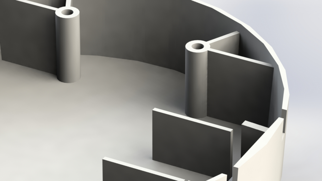
Bosses
Bosses are very common method of creating an attachment point in injection molding. They are simply cylindrical extrusions that can accommodate a self-tapping screw, metal threaded insert or feature from another part.
Metal threaded inserts can be added into the boss by ultrasonic, thermal or in-mold insertion. These allow machine threads and are well suited to higher load applications or which require many cycles of assembly and disassembly.
Best design practice for bosses are as follows:
-Outside diameter 2 times the internal diameter.
-Add chamfer to guide screw or insert into hole.
-The hole should extend to the wall level.
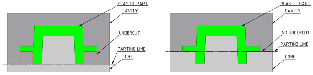
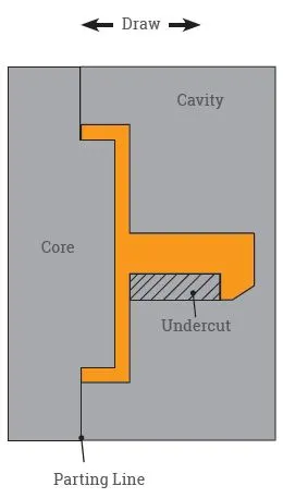
Undercuts
Achieving success with undercuts requires minor mold modifications and a lot of expertise. Some of the designs that can help avoid defects and wearing of the mold include:
Parting Lines: By moving the parting line and adjusting draft angles to intersect an undercut, you can prevent part defects. The parting line placement is limited according to the geometry, material flow, and other features of the part.
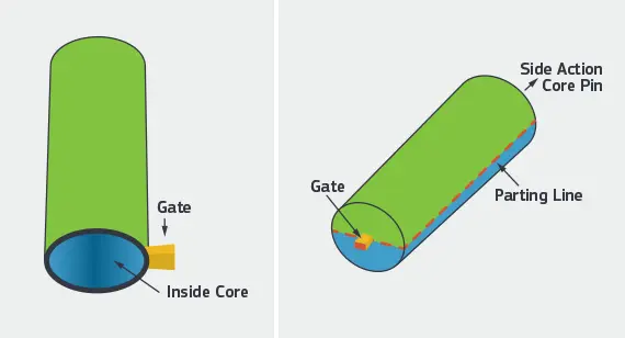
Side-Actions: A perpendicular side-action is ideal for cylindrical parts, as the mold is split horizontally along the part. After the resin is shot into the mold and begins to cool, the side-action slides on an angled pin until its clear from the undercut, allowing it to be freely ejected.
Sliding Shutoffs: This technique uses create clip- and hook-style components to lock together two halves of a mold. During mold operation, these mechanisms seal together, “shutting off” certain areas of the part to create complex features, such as holes.
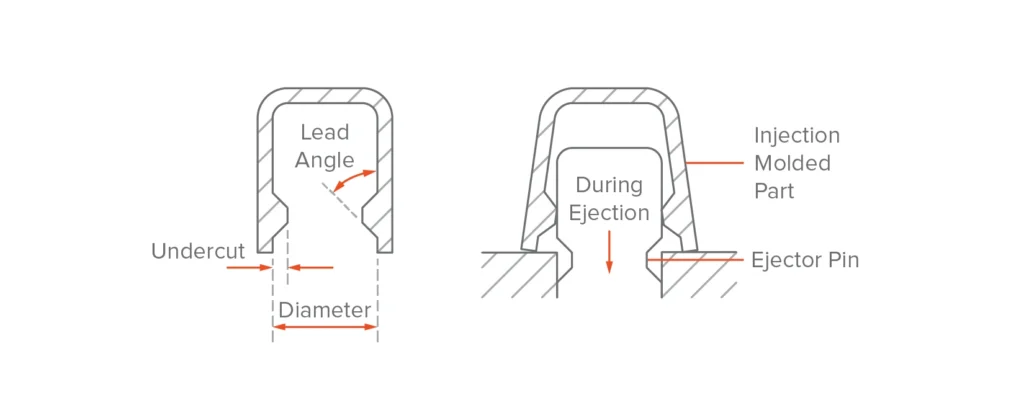
Bump Offs: If you have a mild undercut, you can make a separate insert that bolts into the mold. Upon ejection, the plastic briefly stretches over the insert but subsequently resumes its desired form.
Hand-loaded Inserts: A machined insert is hand-loaded into the mold to prevent molten plastic from flowing into these areas. Upon completion of the cycle, the inserts are ejected with the part, where an operator is required to pick them off the part for further use.