Top-10 Injection Molding Defects And How To Fix Them
Plastic injection molding requires rich experience and knowledge to be dealt with, many factors related to the mold, the machine, the molding process, and the material properties all come into play in this process, some injection molding defects may appear if not handled with properly.
However, if you are the customer who want to work with factories, you need to pay attention to some molding defects than the others, because some obvious defects, like short shots and burn marks, will be surely avoided by the manufacturers because they are so obvious and should be clearly recognized as unacceptable. What you really need to be cautious about is those minor defects that some manufacturers may ignore, so you should verify with the manufacturer to make sure which defects should be avoided before starting.
Resin and Additive Caused Defects
Delamination
If you find that the thin layers easily break or peel off the underlying material on the surface of a molded component, you can see a molding defect called delamination. Delamination, equivalent to what you will usually see on flake mica, is a defect marked by a flaking surface layer. In general, this is considered a reasonably significant defect since it decreases the component’s power.
Causes:
Contamination of the resin pellets or another base substance with foreign material is the most common source of delamination. The effect of flaky separation is where the two materials do not bind together with each other.
For instance, a typical base plastic such as acrylonitrile butadiene styrene (ABS) may be mixed with an incompatible plastic such as polypropylene (PP). If the component is intended for a safety-critical use, the resultant lack of strength of the material will be very unsafe.
Aside from material fed into the hopper, any excess release agents coating the mold for easier separation of components could also be the contaminant. Moisture content on the material may also induce delamination, due to insufficient drying after use. If you detect delamination impacting your molded pieces, take the following corrective steps to avoid reoccurrence:
Remedies:
-If excess moisture is a concern, increase the mold temperature or pre-dry the material correctly.
-Ensure that the resin pellets or base material are correctly processed and treated by staff to avoid pollution.
-Take into account redesigning the mold to minimize the reliance on release agents by relying on the injection nozzle.
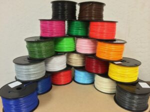
Discoloration
Where a molded component is a different shade than expected, discoloration, or “color streaking” happens. Sometimes, the decoloration on a molded component is confined to a small spot or a handful of stripes of irregular pigment. The visibility of the component is usually influenced by this defect without reducing its intensity.
Causes:
Possible factors are low thermal stability of the coloring agent or excessive masterbatch blending. To minimize the chance of discoloration in your injection-molded products, take the following precautions:
Remedies:
-Ensure the workers during manufacturing thoroughly cleans the hopper, nozzle, and mold to remove any remaining pellets or base content.
-To extract unwanted color from the unit, try using a purging compound to guarantee that a paint agent with sufficient thermal consistency is used by you or your supplier.
-For consistent color production, assure that the masterbatch is mixed uniformly
Mold-Caused Defects
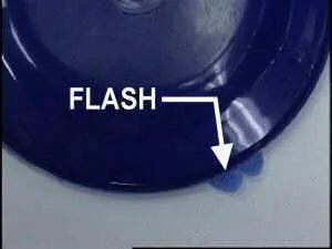
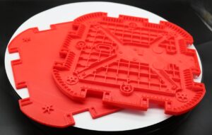
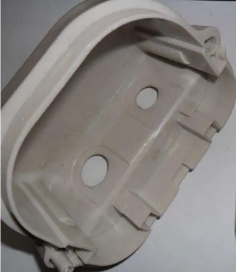
Flashes or too noticeable parting line
Flash are irregular excessive material (usually in the form of thin-film) on the plastic parts that escape from the mold cavity. They usually appear along the parting line or any other place where there is a gap between moving parts inside the mold.
Cause:
An injection mold consists of an upper mold and lower mold when they are pressed together form the enclosed cavity. However there may be a slight gap between them due to inaccuracy of machining, or because of the inside pressure overcome the clamping force. At the same time, there are moving components like sliders, ejector pins in the mold, they all have slight gaps around them. The gap is totally allowed and even helpful for the gas vent. However, when the gap is greater than the limit of the viscosity allows of the molten material, it will leak into the gap and form the flashes. The impact of flash is mostly aesthetical.
Remedies:
-Increase the precision of mold manufacturing to have smaller and consistent gaps in moving components;
-Use a bigger injection machine (with a higher tonnage) so as to get greater clamping force;
-Lower the packing pressure and temperature;
-Change to higher viscosity material (less flowability).
Short Shot
A short shot happens where the flow of molten fluid does not occupy the cavities in a mold properly. The effect is that, after cooling, the molded part is incomplete. For example, the short shot may appear as incomplete compartments in a display’s plastic shelves or missing prongs on a plastic fork. Typically, short shots are categorized as a severe defect that may inhibit function or presentation.
Causes:
Flow constraints arising from small or blocked gates are the most frequent source of short shots. The liquid is often too viscous or the mold is too cool to enable the molten material to cover the mold sufficiently before cooling. As well as other occasions, stuck air pockets may impede proper flow or it may be insufficient to inject pressure. To avoid short shots, take the following steps:
Remedies:
-Redesign the mold for improved flow with larger channels or gates
Raise the speed or pressure of the injection or choose a thin base material to boost the flow
-To prevent material from cooling too fast, raise the temperature of the mold
-To allow trapped air to escape, install additional air vents or expand existing vents in the mold
Process-Caused Defects
Despite continual advances in injection molding technology, process-derived injection molding defects still occur.
|
Burn Marks
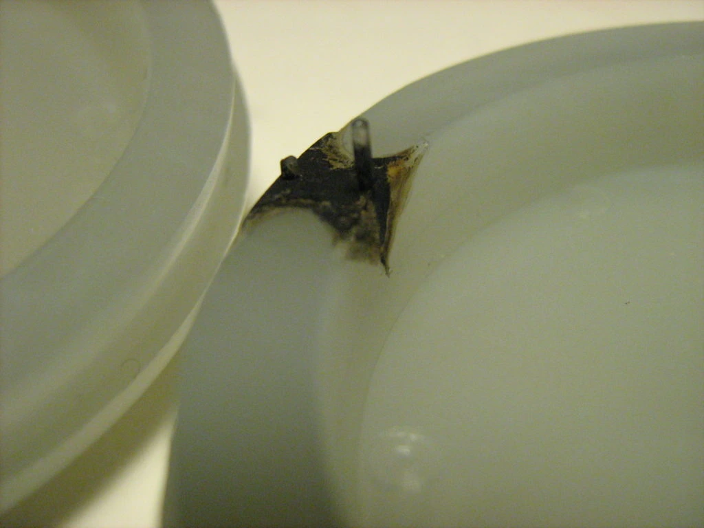
Burn marks normally occur on the edges or surface of a molded plastic component as black or rust-colored decoloration. Injection molding defects. Burn marks usually do not impact product functionality until the plastic is burnt to the point of corrosion.
Cause:
Trapped air, or the resin itself, overheating in the mold cavity during injection, is the normal source of burn marks in injection-molded sections. Extreme rates of injection or substance warming sometimes contribute to excessive heat that induces burns.
Remedy:
-Stop heat stress, minimize the temperature of the melt and mold
-To reduce the risk of trapping air on the inside of the mold, reduce the injection velocity
-Increase the size of gas vents and gates to enable the mold to resist trapped air
-Reduce the mold cycle time so there can be no risk of overheating any trapped air and resin.
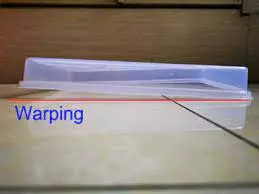
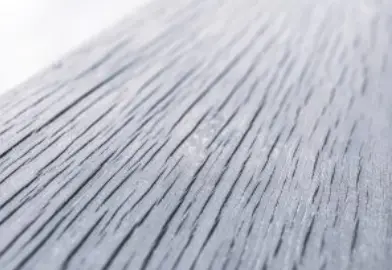
Warping
Warping is a deformation that can develop as various portions of a component compress irregularly in injection-molded products. Same as wood can distort as it dries inconsistently, as irregular shrinkage places excessive stress on various parts of the molded component; plastic and other materials can deform during the cooling process. Bending or turning of the completed component as it cools is a result of this undue tension.
Causes:
An injection-molded plastic and related materials, several of the key reasons for warping are that cooling occurs too fast. The issue can indeed be exacerbated by high temperatures or poor thermal conductivity of the molten material.
In other instances, where the walls of the mold are not of uniform thickness, mold construction will lead to warping. Shrinkage increases with wall thickness. In your molded bits, here are some common ways to avoid warping:
Remedy:
-Ensure that the cooling process is slow and lengthy enough to reduce uneven material stresses
-Lower the substance or mold temperature
-Try converting to a substance that during cooling tends to shrinks less (e.g. particle-filled thermoplastics shrink much less than semi-crystalline materials or unfilled grades)
-To ensure greater stability in the component during cooling, redesign the mold with uniform wall thickness and part symmetry
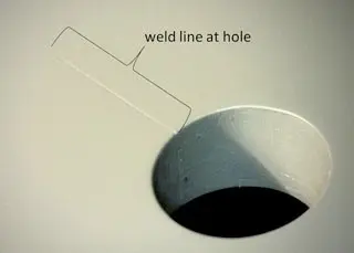
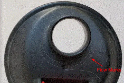
Weld line
Weld lines, or knit lines, are hair-like thin lines (sometimes comes with discoloration) on plastic parts, usually on one side of holes (or similar features). They can be straight or curved, but they are quite regular in shape.
Weld lines are very common in plastic parts and can hardly be completely avoided. They are acceptable if controlled at a minimal level. We just need to define to what level the weld lines are acceptable for a plastic part.
Cause:
When molten plastic is injected into the mold cavity, they will be forced to be divided into 2 flows when meeting an obstacle like a hole (which is a post inside of the mold), then the separated flows will meet at its downstream, or on the other end of the hole. During this process, the molten plastic gets partially solidified, which will cause the flows cannot merge so well together.
When this partial solidification becomes worse, discoloration will happen.
Remedy:
-Increase the mold temperature, use a mold heater (there will be a bit of cost increase).
-Increase the mold and cylinder temperature.
-Increase the filling speed.
-Change the plastic material that is less sensitive to weld lines.
-Optimize the mold design.
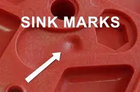
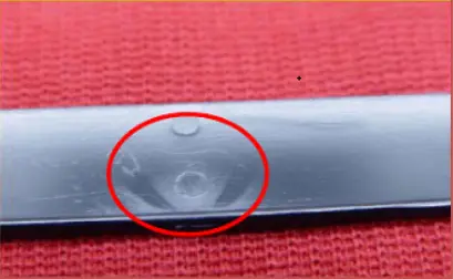
Sink marks
Sink marks are small recesses or depressions in an otherwise flat and consistent surface of a molded part. These can occur when the inner part of a molded component shrinks, pulling material from the outside inward.
Cause:
When the molten plastic flows into the cavity, it starts to cool and solidify. At the same time, it shrinks (gets smaller in size). In the thick-wall area, the inside material cools and hardens later than the surface. If the inside shrinkage is not compensated with the new flow of material (after the gate freeze), then it will pull the surface inwards and forms a depression. If the surface is too hard, voids will be formed inside.
Remedies:
-Optimize part design with thinner component walls to allow for faster cooling near the surface;
-Increase the packing pressure and time;
-Lower the mold and molten plastic temperature;
-Put the gate in the thick-walled section and enlarge the gate size, so as to allow better material compensation in the cooling and solidifying process;
-Conduct mold flow analysis before starting making the mold.
-Change the material which is less sensitive to shrinkage.
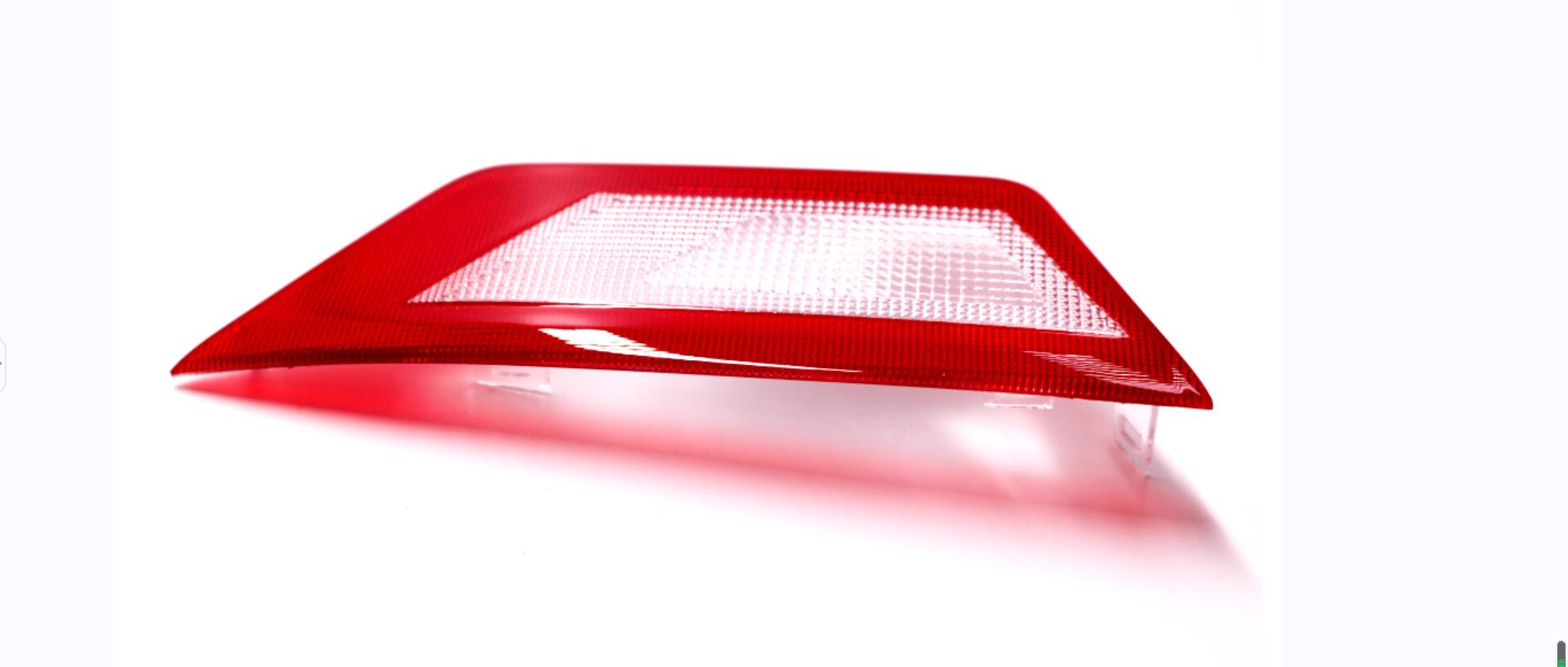
Vacuum voids and air bubbles
Vacuum voids and air bubbles are similar in appearance and can be often be confused with each other. They are both bubbles inside of a plastic injection molded part.
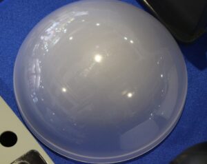
For transparent parts the bubbles are an aesthetic or functional issue, for example, for LED lenses, even the smallest bubbles are not acceptable. At the same time, bubbles can sometimes weaken the mechanical strength, thus we also need to check if the weakening will cause any problem for their specific application.
However, sometimes when strength is not a concern, the voids and bubbles is not a big issue for opaque plastic parts.
We can do a heat test to check what kind of bubbles they are, use a heat air gun to heat and soften the plastic, if the bubbles grow bigger, then they are air bubbles, if they collapse (or become smaller), then they are vacuum voids.
Although they are quite alike, the reasons and countermeasures are different:
1. Vacuum voids
Cause:
The mechanism for the formation of vacuum voids are quite similar to sink marks. The outside material gets cooled and solidified first, while the inside material still continues to cool down and shrink, at first it will get compensated with the new material flow from the gate. After the gate freezes, there will be no material compensation anymore, and if the outside material is too hard to be pulled inwards, then the voids will form.
Remedies:
-Optimize part design, make the walls thinner if possible
-Increase the packing pressure and time;
-Lower the mold and molten plastic temperature;
-Widen the gate. Locate the gate in the thick-walled section so as to allow better material compensation;
-Change the material which is less sensitive to shrinkage.
2. Air bubbles
Cause:
When the injection filling speed is too high, or the plastic part has very thin walls, or sometimes when the mold vent is not adequate, it will cause the air to be trapped inside of the plastic part and form the air bubbles.
Remedies:
-Slow down the filling speed,so as to avoid air trap in the mold;
-Improve the vent of the mold.
-Dry the material completely before injection molding;
-Make sure the cylinder screw work properly not to mix air in the molten plastic;
-Do not overheat the plastic in the tank or stay too long, this may cause decomposition of resin and form gas.