English
 Deutsch
 Español
 Français
 Italiano
 日本語
 Русский
 中文
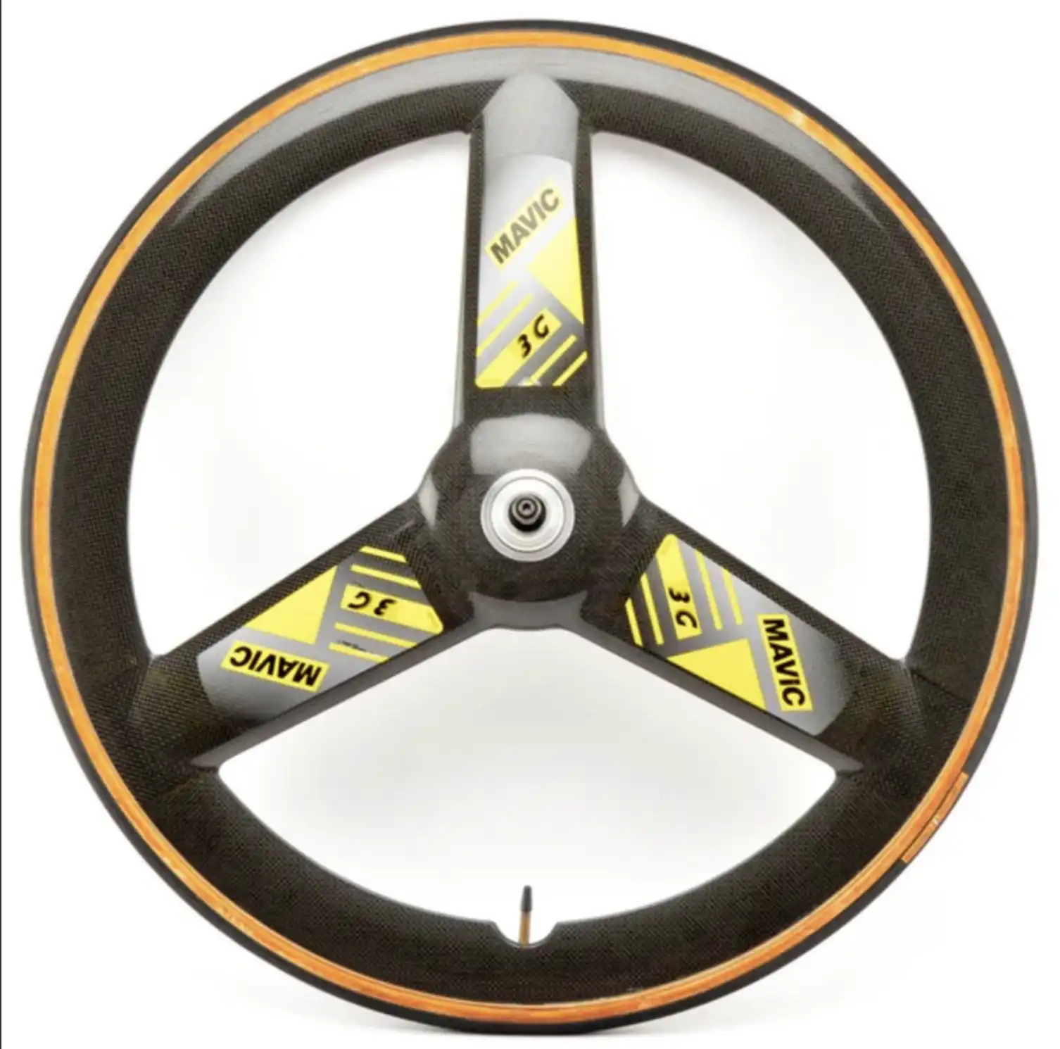
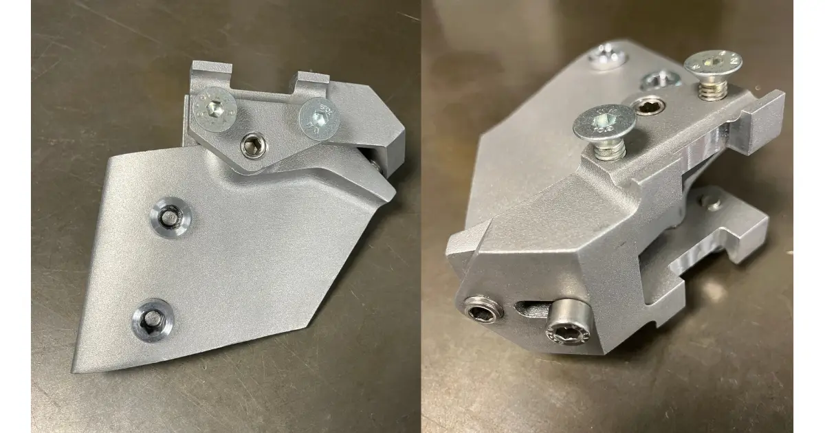
Lotus 110 Saddle Clamp Redesigned with Metal 3D Printing
- Published August 14 2026 - Updated November 02 2026
Discover how an additive manufacturing engineer recreated a discontinued Lotus 110 saddle clamp using 3D scanning, reverse engineering, and metal 3D printing.
Project story by @Mavic_3G , with IN3DTEC production notes.
As an additive manufacturing engineer and cycling enthusiast, I've wanted to combine my work with my passion for bicycles since my university days and create something of my own.
THE LOTUS 110 AND ITS SADDLE CRADLE
At the 2021 Tokyo Olympics, the HB.T track bike, a collaboration between Lotus and Hope, caught my eye. Its use of 3D-printed titanium components for complex structural parts showed me the potential of additive manufacturing in the cycling industry. It also brought my attention back to another iconic Lotus bike: the Lotus 110, which was famously banned by the UCI for its radical design.
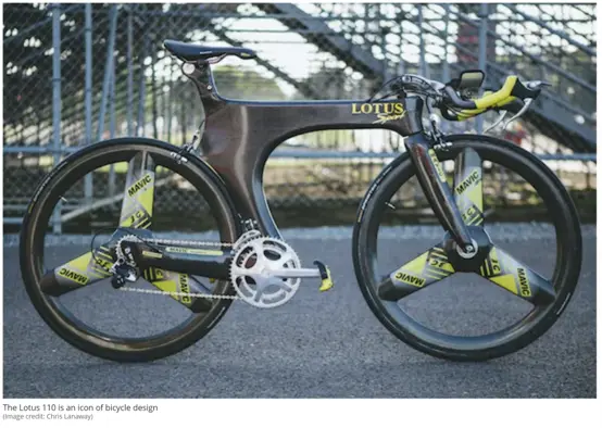
The Lotus 110, known for its distinctive Z-shaped monocoque frame and aerodynamic design.
Image source: Cyclist.com: https://www.cyclist.co.uk/in-depth/lotus-110-bike
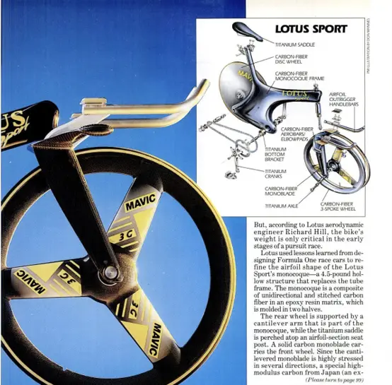
A vintage technical illustration showing the Lotus Sport frame layout and specifications.
https://villaveloframes.wordpress.com/2018/02/28/quangs-lotus-sport-110-ex-ais-part-1/
With its distinctive Z-shaped frame, the Lotus 110 remains a classic example of aerodynamic engineering. It is a design admired by many, myself included. What interests me most, however, is the unique structure connecting the seatmast to the saddle, which I refer to as the saddle cradle.
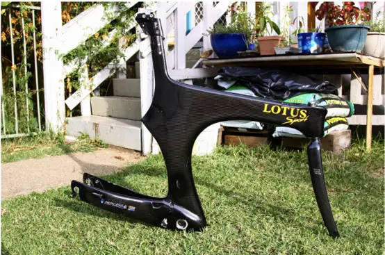
The integrated seatmast forms the mounting point for the saddle clamp assembly.
https://villaveloframes.wordpress.com/2018/02/28/quangs-lotus-sport-110-ex-ais-part-1/
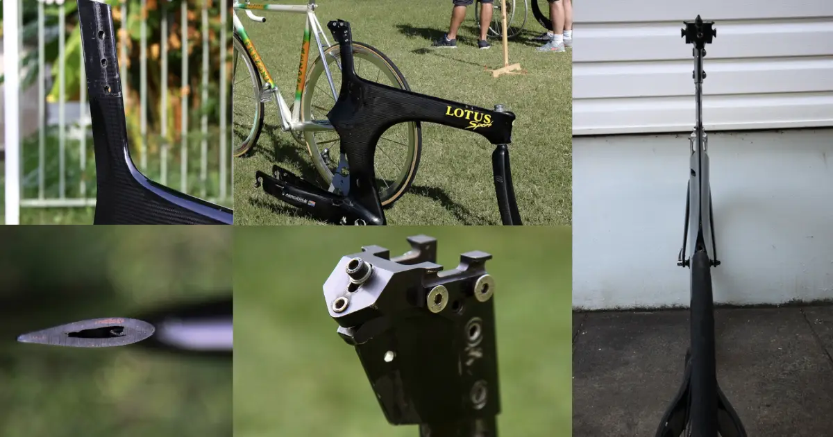
Close-up details of the original assembly, including the Seatmast Cap and Saddle Rail Clamp.
https://villaveloframes.wordpress.com/2018/02/28/quangs-lotus-sport-110-ex-ais-part-1/
Unfortunately, the bike has long been out of production, making original parts and suitable replacements difficult to find. Finding one would be even harder if I wanted to adapt it for a custom-built bike of my own.
"If additive manufacturing can already be used for complex bicycle designs use it to recreate the Lotus 110 saddle cradle thought out of my head.
UNDERSTANDING THE ORIGINAL LOTUS 110 SADDLE CRADLE DESIGN
What appeals to me most about this saddle cradle is how it uses a series of well-designed mechanical connections for mounting, securing, and adjustment.
It consists of two main components. The first is the seatmast cap, which attaches to the seatmast with two screws. Together with the oval-shaped mounting holes on the seatmast, this allows for minor height adjustments. A separate pair of set screws also press against the seatmast to further secure the cap in place.
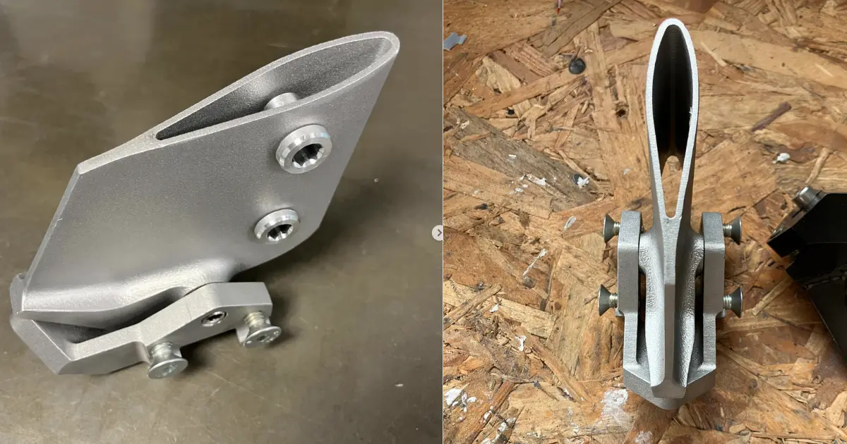
Top and side views showing the geometry and screw-mounting holes of the printed Seatmast Cap.
Source: @Mavic_3G
The second component is the saddle rail clamp, which features a unique clamping mechanism. The original part is machined from a solid block of aluminum. It uses four bolts to secure the saddle rails between the bolt heads and the clamp lugs.
Compared with the internal wedge-based locking systems and concealed clamps commonly used today, this design has more direct and visible mechanical connections.
REVERSE ENGINEERING A DISCONTINUED BICYCLE PART
But I faced one challenge: I wanted to recreate a vintage part _ out of production for years, preserving its original shape, structure, and details as closely as possible. However, I didn't have the original engineering drawings or CAD files. So, how could I get the 3D data I needed?
I turned to 3D scanning. Fortunately, through a cycling community, I connected with a Lotus 110 owner who was willing to lend me their original saddle clamp assembly for scanning and measurement.
With the original part in hand, the next step was to turn it into a digital model for manufacturing through reverse engineering.
I used 3D scanning to capture its geometry, then took physical measurements to check key dimensions and structural details. After processing and analyzing the scan data, I reconstructed an editable CAD model.
This involved more than just copying the part's outer shape. I also had to identify how it connects to the frame, where the saddle rails are clamped, and how the different components fit together.
Since the original saddle cradle already consisted of two separate components, my goal was to reproduce their original shapes and structures as closely as possible. I prepared the CAD models for metal 3D printing and subsequent post-processing, including drilling and screw assembly.
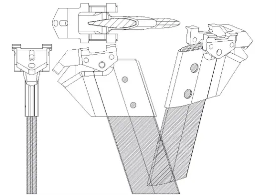
CAD assembly reconstructed from 3D scan data and physical measurements
Source: @Mavic_3G
RECREATING THE SADDLE CRADLE WITH METAL 3D PRINTING
With the CAD model ready, the next step was to choose the manufacturing process. Typically, metal 3D printing starts with a 3D CAD model. The model is then processed using slicing software to generate instructions for the printer. The machine builds the physical part by melting metal powder layer by layer.
Using IN3DTEC's online platform, I selected an aluminum alloy, chose Selective Laser Melting (SLM) for printing, and opted for glass bead blasting as the surface finish.
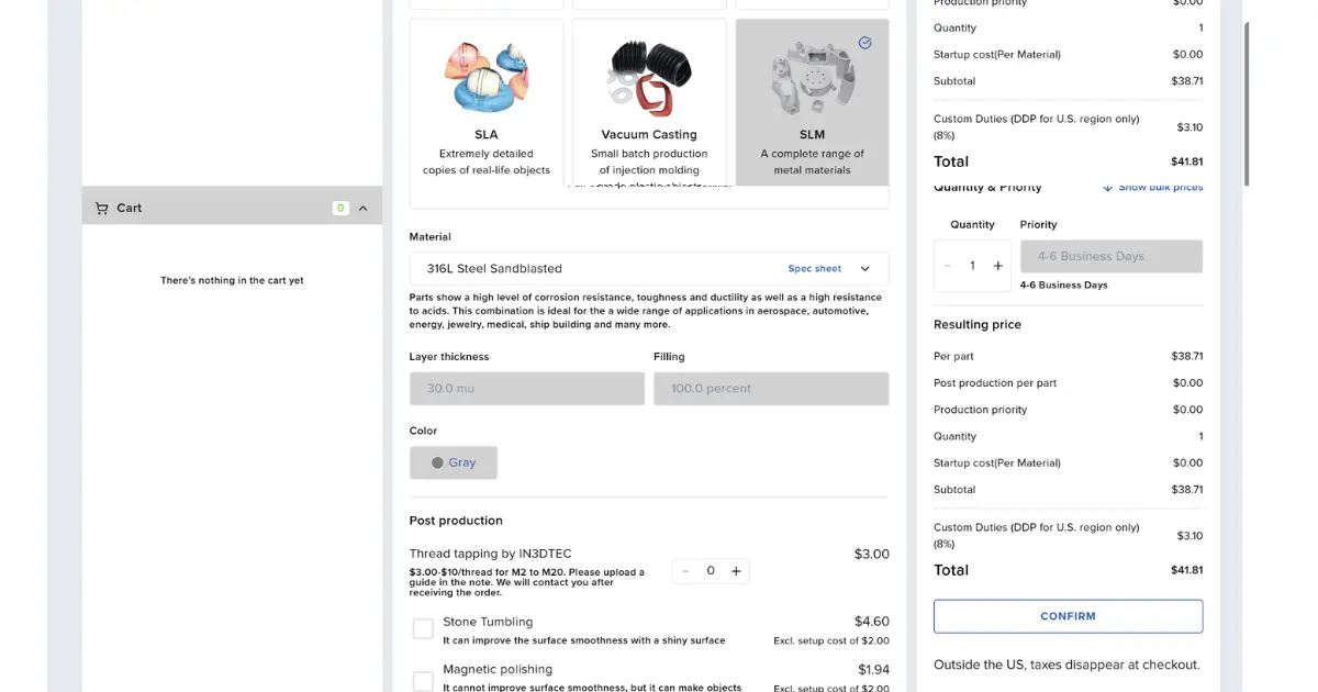
Selecting an aluminum alloy, SLM printing, and glass bead blasting on IN3DTEC's online platform.
Source: www.in3dtec.com/online-quote
POST-PROCESSING AND ASSEMBLING THE 3D-PRINTED PARTS
I was very pleased with the printed parts when they arrived. But the manufacturing process didn't end there.
IN3DTEC also offers remachined services for features such as holes and connection points. However, as an engineer, I wanted to handle some of this work myself. I enjoy getting hands-on with these details.
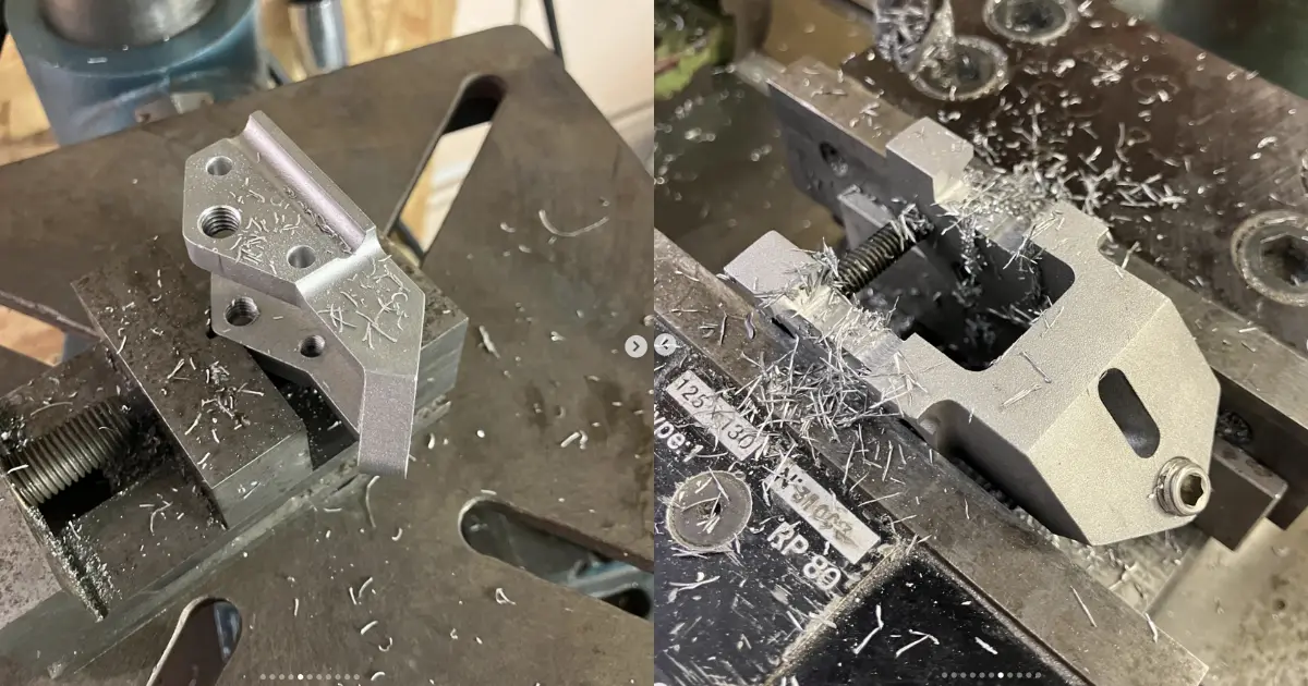
A drill press is used to finish the connection holes before screw assembly
Source: @Mavic_3G
During the CAD design stage, I had already included holes for connecting the two separate printed parts with screws. Once I received the parts, I used my own drill press to finish the connection holes, then fastened the two pieces together with screws to complete the saddle cradle.
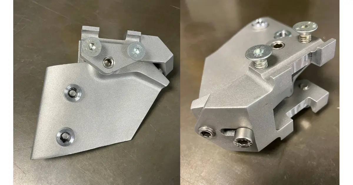
The two printed components fastened together with screws to complete the assembly.
Source: @Mavic_3G
From metal 3D printing to drilling and screw assembly, the process combined additive manufacturing with machining. Being involved in these finishing and assembly steps was one of the most enjoyable parts of the project for me.
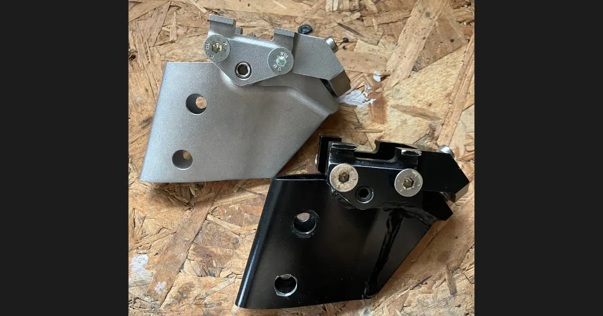
Side-by-side comparison of the original assembly and its 3D-printed aluminum replacement.
Source: @Mavic_3G
The finished silver aluminum alloy part is displayed alongside the original black assembly, making it easy to compare their appearance and structure. The new part retains the key geometric features and mechanical connections of the original design. Once assembled, it was also mounted onto the seatmast, showing how it fits with the bicycle's existing structure.
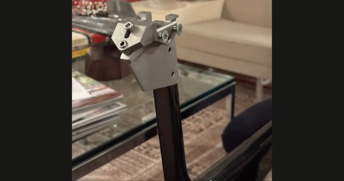
The finished saddle clamp assembly mounted on the Lotus 110 seatmast.
Source: @Mavic_3G
METAL 3D PRINTING FOR DISCONTINUED REPLACEMENT PARTS
This project shows how metal 3D printing can offer a new way to reproduce classic or discontinued parts. When original drawings or CAD files are unavailable and replacement parts are hard to find, reverse engineering combined with metal 3D printing makes custom, one-off, and small-batch production possible.
By the way, you don't need experience in reverse engineering to take on a project like this. Manufacturing service providers like IN3DTEC can offer support throughout the process, from 3D scanning and reverse engineering to CAD modeling, metal 3D printing, and post-processing. You can provide the original part and let the team handle the process. As an engineer, I enjoy working on the technical side myself, so I chose to handle the scanning and design work for this project.
For me, the most rewarding part was bringing back a classic bicycle component that I have admired for years. It was also a chance to bring my professional experience and personal interest together, while getting hands-on with different manufacturing processes.
Explore more in Instagram: