White paper of HP Multi Jet Fusion

How does HP Multi Jet Fusion work?

Introduction

HP Multi Jet Fusion (MJF) technology is a powder-bed fusion 3D printing technology that allows for the production of accurate, functional prototypes and final parts, including color parts. In addition, HP MJF is a technology that does not require support structures, thus enabling the design of complex geometries without additional costs, which would be expensive or not even possible to produce with traditional manufacturing processes.

HP MJF 3D printing process

The HP MJF 3D printing process begins with a thin layer of uniformly pre-heated polymer powder particles that is spread across the build platform.

Then, to achieve part quality at a high speed and produce truly functional parts, HP MJF technology uses the HP multi-agent printing process. HP’s in-depth knowledge of 2D printing solutions and the capability of HP’s proprietary architecture makes it possible to
print millions of drops per second along each inch of the bed width, thus enabling extreme precision and dimensional accuracy.

HP Multi Jet Fusion’s multi-agent printing process can control the exact amount of each agent that is deposited in each voxel of the intended part. This printing process involves two different types of agents that are applied across the build platform: fusing agents
and detailing agents.

A fusing agent is applied where the particles are meant to fuse together in the powder in order to create the corresponding part cross section, leaving the rest of the powder unaltered. A detailing agent is applied to the edges of the part in order to modify the
fusing process and create fine detail and smooth surfaces.

Next, an energy source passes over the build platform, provoking a reaction between the agents and the material that causes the material to selectively fuse to form a complete layer, thus resulting in production throughput, material density similar to common Injection Molded plastics, and consistent mechanical properties in all directions.

The process is then repeated until a completely functional part has been formed.
The 3D printing process using HP MJF is summarized in the following figure:

Post processing for HP Multi Jet Fusion Technology

MJF is a new technology that delivers certain advantages over legacy print processes, but there are still post-processing steps that are required before items can be considered finished. Worth noting, however, is that the HP Jet Fusion 3D Processing Station has the option of “Fast Cooling,” which allows prints to be cooled down more quickly so that they may be removed for more immediate processing. In addition, the latest HP Jet Fusion 5200 3D Printing Solutions include a Natural Cooling Unit designed for economical continuous printing.

Within the processing station for the Jet Fusion 4200 and 5200 systems, there is a vacuum used to remove powder. Once removed from the processing station, bead blasting, airblasting or waterblasting is performed to clear any remaining powder, not unlike SLS.

Bead Blasting: This process consists of shooting an abrasive media, usually a bead (size and type results in different surface finishes), at high pressure at a printed part with compressed air, knocking loose unfused powder while also smoothing the finish of the part. This can be done manually or automatically, with manual bead blasting relying on a foot pedal-driven system for propelling the beads as opposed to an automated tumbler, turntable or conveyer. Manual may be preferred for fragile parts.

Water Jet Blasting: This process features the jetting of water and air onto a part to remove powder and can include the use of a blast media for preliminary surface finishing. Typically more expensive than bead blasting, this process is ideal for complex geometries and cavities automatically while also reducing surface roughness without the need for additional post processing (such as a vibratory system). No dust is produced, as well.

Airblasting: Air blasting is necessary after bead blasting, but not water jetting, and some bead blasting machines have air blasting capabilities. After bead blasting, air blasting must be used to remove the remaining powder from the surface of the printed part using a closed cabin air pressure machine with a minimum air pressure of three bar.

Secondary Post-Processing

After the necessary post-processing steps described above, parts may need further finishing to bring the part up to technical requirements. This includes methods for reducing surface roughness, as well as methods for changing the color or finish of the part, like dying, electroplating and painting.

Sanding: Post-processing techniques can range from manual to almost entirely automated. For example, a company may want to smooth their Multi Jet Fusion parts; this could be done with manual sanding, though it would take a long time and be cost-prohibitive. However, it may work for one-off objects or visual prototypes.
Vibratory Tumbling: “Vibratory tumbling is another method that can be used to smooth Multi Jet Fusion parts that is hands-off and largely automated,” she added. “Though it can take several hours, because the process does not require supervision and can process many parts at once it is very cost-effective. You can buy vibratory tumblers of different sizes, according to your particular specifications such as quantity and part size.”

Vibratory finishing can be performed as a wet or dry process. In wet vibratory tumbling, ceramic and plastic media are used and create a more polished finish, with less wear on the part, but produces waste from the liquid-abrasive media. The dry process is cleaner and wastes less, but may be more aggressive.

Chemical polishing: This process uses a chemical to smooth the surface of printed parts without impacting its mechanical properties, resulting in a controllable level of glossiness from matt to gloss to shiny.

Dying: In addition, not unlike other processes, MJF parts can be subject to any number of finishes. Though there is an MJF line dedicated to full-color 3D printing (HP Jet Fusion 580/380 series), these systems are currently designed for smaller batches. When coloring parts that haven’t been printed on those machines, dying can be performed, either manually in pots of hot water or using automated dying equipment. 

Dyeing is the most common secondary post-processing technique of MJF users and may be best for parts that are visible or subject to wear, as the color penetrates the surface of the part. Dying white parts, rather than grey, offers a greater range of dying options. Manual dying, which usually involves leaving the part in an 80-100°C dye bath for about eight minutes, is comparatively inexpensive. Automated dying machines, however, may be more efficient, as they use specific programs for mixing the dye bath, as well as conditioning, dyeing, part rinsing, dye disposal, and cleaning.

Part with dying
Painting and Electroplating: Painting and plating are other options for coating Multi Jet Fusion parts. Performing surface smoothing first will help achieve the best results with the least additional effort. Since every industry has its own paint specifications, the best bet is to have samples done with existing paint suppliers. Hydrographs are another method of coating. An image or pattern is floated on water, and the part is dipped in it to transfer the pattern over. Given that a layer of material is applied in the process, hydrographs also result in a smoother surface. 
Part with painting

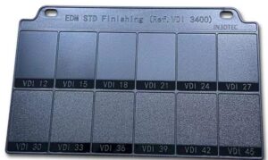
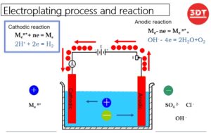
Electroplating consists of dissolving a metal in a solution and attaching the metal particles to the surface of the printed part using an electric current. Before this process can be performed on a polyamide part, the part must be made electrically conductive through the use of electroless plating, gas activation, or a conductive coating.

Graphite Blasting: Graphite blasting uses the same process as bead blasting but aims for giving parts a uniform, metallic appearance, with glass beads and graphite projected at the part. This can also reduce friction between moving parts, though it is not recommended for final parts that are handled frequently.

MJF materials and selection guide

MJF materials

Polyamide family

Nylon PA12
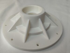
PA 12 is a strong, multi-purpose thermoplastic for functional prototyping and final parts. It is optimized for the MJF platform to deliver high-density parts with balanced property profiles. It is ideal for complex assemblies, housings, enclosures and connectors, and optimal for post finishing processes. PA 12 also has excellent chemical resistance to oils, greases, aliphatic hydrocarbons and alkalis.

Nylon PA12 with Glass Beads
Glass Beads are added to Nylon PA 12 to produce stiff, functional parts. This material provides dimensional stability along with repeatability. It is ideal for applications requiring high stiffness like enclosures and houses, fixtures and tooling.

Nylon PA11
Nylon PA11 is a material with excellent performance characteristics that mitigates many of the negatives inherent to other materials. With excellent impact and chemical resistance and an eco-friendly and bio-friendly profile, here are six reasons to consider Nylon PA11 for your project.

ECO-FRIENDLY: This is a bioplastic polyamide powder made out of renewable resources that come from vegetable/castor oil.

CHEMICAL RESISTANCE: Chemically resistant to elements such as hydrocarbons, ketones, aldehydes, fuels, alcohols, oils, fats, mineral bases, salts, and detergents.

IMPACT RESISTANCE: Since PA11 offers superior impact and abrasion resistance, parts will have a longer serviceable lifetime

HEAT DEFLECTION TEMP: With a HDT of 350 F, it will maintain optimal mechanical properties even in extreme environments

STRONG & FLEXIBLE: Known for its optimal mechanical properties. Ideal for prostheses, insoles, sporting goods, and more.

BIOCOMPATIBLE: Meets requirements of USP Class I – VI and US FDA guidance for Intact Skin Surface Devices.

Polyurethane family

TPU (Thermoplastic Polyurethane)

3D Printed elastomer parts can be used in place of traditionally molded rubber for just about any 3D printed application. And, now, with this specially optimized TPU (Thermoplastic Polyurethane) elastomeric powder, designed for HP’s Multi Jet Fusion (MJF) technology, we can further accelerate the already fast processing times of MJF printers.

Parts created from TPU offer excellent accuracy, unlimited design possibilities, high flexibility and shock absorption, and a well-balanced strength profile. And, with our in-house vapor smoothing technology, we can manufacture parts that are more flexible, stronger, water resistant, and with a surface finish more like that of injection molding.
Ideal Applications for 3D Printed TPU

-Gaskets, Seals, Connectors & Hoses
-Lattice Design Structures
-Robotics
-Automotive Instrument Panels, Shock Absorption
-Bellows & Ducting
-Isolation Dampers
-Harnesses & Fasteners
-Functional Prototypes
-Footwear & Sporting Goods
-Medical Components

Choosing the right material for mechanical requirements

STEP 1: Select a material with generic properties according to key attributes. In thermoplastics, the most commonly used properties are tensile strength, tensile modulus, and elongation, (but others may also be considered).

• Tensile strength measures the resistance of the material to breaking under tension.
• Tensile modulus measures the rigidity or resistance to elastic deformation.
• Elongation measures the deformation (elastic or plastic) that a part undergoes given a certain strain.

STEP 2: Once a material has been selected, the design of the part needs to be performed in line with HP Multi Jet Fusion design guidelines, allowing enough of a design margin (two or three times, depending on the property) to accommodate for all possible variations in the part itself or in the application-specific conditions.

STEP 3: Even after the design has been performed according to these principles, it is highly advisable to conduct a full application-specific qualification to ensure the precision of the design, obtain validation data that represent the application’s end-to-end performance, and characterize its variation over time or according to other production and application variation factors.

Design guideline

Cantilever
When printing a cantilever, the minimum wall thickness depends on the aspect ratio, which is the length divided by the width. For a cantilever with a width of less than 1 mm, the aspect ratio should be less than 1. There are no specific recommendations for widths of 1 mm or larger. For parts with a high aspect ratio, it is recommended to increase the wall thickness or to add ribs or fillets to reinforce the part.

Wall thickness
In general, the minimum recommended wall thickness is 0.3 mm for short walls oriented in the XY plane, and 0.5 mm for short walls oriented in the Z direction.
Connecting parts
Sometimes a pair of printed parts need to fit together to form the final application. To ensure correct assembly, the minimum gap between the interface areas of these parts should be at least 0.4 mm (±0.2 mm of tolerance for each part).
Moving parts
As a general rule, spacing and clearance between faces of printed as assemblies should be a minimum of 0.7 mm.
Thin and long parts
Long and thin parts have the potential to warp. Generally, any part that has an aspect ratio higher than 10:1 is susceptible to warpage.
– Increase the thickness of the part.
 – Add ribs in the areas that may be affected.
 – Replace the solid volume with a lattice structure as in the “Lighter Design” shown.
 – Reduce sharp transitions, as shown in the “Smooth Transition” shown.

What is the difference between MJF and SLS

Multi Jet Fusion’s biggest direct competitor in the powder bed 3D printing space is selective laser sintering (SLS). On a superficial glance, they are quite similar – both use a heated chamber in which individual material powder layers are fused together without the need for support.

But whereas MJF uses inkjet-dispensed agents and a heating element, SLS fuses the layers together with a directed laser beam. When we start looking at the more technical details, other major differences quickly pop up.

FEATURE RESOLUTION
MJF printers produce prints in layers 0.0003 inches (80 microns) thick, with a minimum feature size of 0.02 inches (0.5mm). This means it can produce finer surface detail than SLS, which has a feature size of 0.03 inches (0.75mm).
That said, Protolabs notes that SLS can provide better small feature accuracy than MJF.

WALL THICKNESS
MJF has a minimum wall thickness of 0.02 inches (50mm), while SLS can produce walls as thin as 0.04 inches (1mm). As such, if thinner walls are a requirement, MJF is the way to go.

PART SIZE
SLS comes on top in part size, with a maximum envelope of 19x19x17 inches against MJF’s 11.1×14.9×14.9 inches. With that said, Multi Jet Fusion should still provide plenty of print size for most 3D printed parts.

MATERIALS
As mentioned, Multi Jet Fusion is currently limited in suitable materials. SLS on the other hand has a much larger compatible materials catalogue, and is therefore the technology of choice if specialty materials are required.

That said, new materials for Multi Jet Fusion are in development as you read this article, so this situation may change at any moment. Additionally, MJF-printed parts provide higher tensile strength than SLS and have much more consistent mechanical properties.

This is where color also comes into play. SLS provides more consistent surface color without additional products, although MJF’s capability for full-color CMYK printing might offset the salt-and-pepper-like gray of the untreated print.

BUILD VOLUME
In build volume, there is no competition. MJF trounces on SLS in print times, making it possible to produce several high-quality prints in the time it takes for SLS to complete one print.

WHICH ONE WINS?
Although it’s not a silver bullet technology, most 3D printing companies have begun to recommend MJF over SLS. The ultimate choice, however, comes down the requirements of each individual project. You should therefore evaluate your needs before making the final decision.

Share:

Facebook
Twitter
LinkedIn
Email

More Posts

The best ABS 3D Printing settings

The Best ABS 3D Printing Settings: Achieving Optimal Results Introduction: ABS (Acrylonitrile Butadiene Styrene) is a popular thermoplastic material widely used in 3D printing due

The Best POM 3D Printing Settings

The Best POM 3D Printing Settings: Achieving Optimal Results Introduction: POM (Polyoxymethylene), also known as Delrin or Acetal, is a high-performance thermoplastic material that offers

The Best Resin 3D Printers in 2024

The Best Resin 3D Printers in 2024: Unleashing High-Quality Printing Potential Introduction: Resin 3D printers have gained significant popularity in recent years due to their

Stay up-to-date

Keep posted on the release of Coupon Code. The latest news of 3D Printing, CNC Machining, Injection Molding, and Silicone Molding…